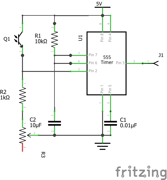
The Hand Controllers will be attached to bats or rackets that the players will swing to hit the “light ball”*. The accelerometer on the Hand Controller will tell me how fast (read: powerful) their swing is, but I still need to know if they timed it right. My original design involved actually hitting something (like a pillow or post), but I decided against that for many reasons. The current design has a vertical laser beam that the bat will pass through, sending a pulse to the Hand Controller’s Arduino to signal the timing of the swing. I’m using a phototransistor and a 555 monostable circuit to generate a long enough pulse for the Arduino to see on a cycle through the code.
(I decided not to use the phototransistor signal to generate an interrupt on the Arduino because I want the player to be able to bunt by holding the bat still in the beam. An interrupt wouldn’t let me know if this was happening, but the 555 circuit will keep it’s output low as long as the beam is blocked.)
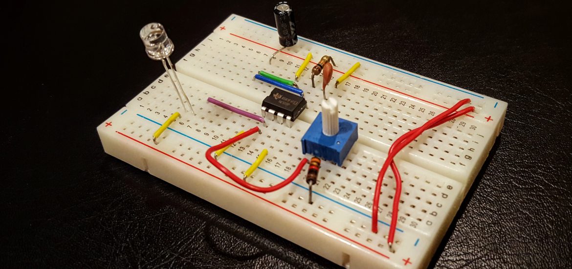
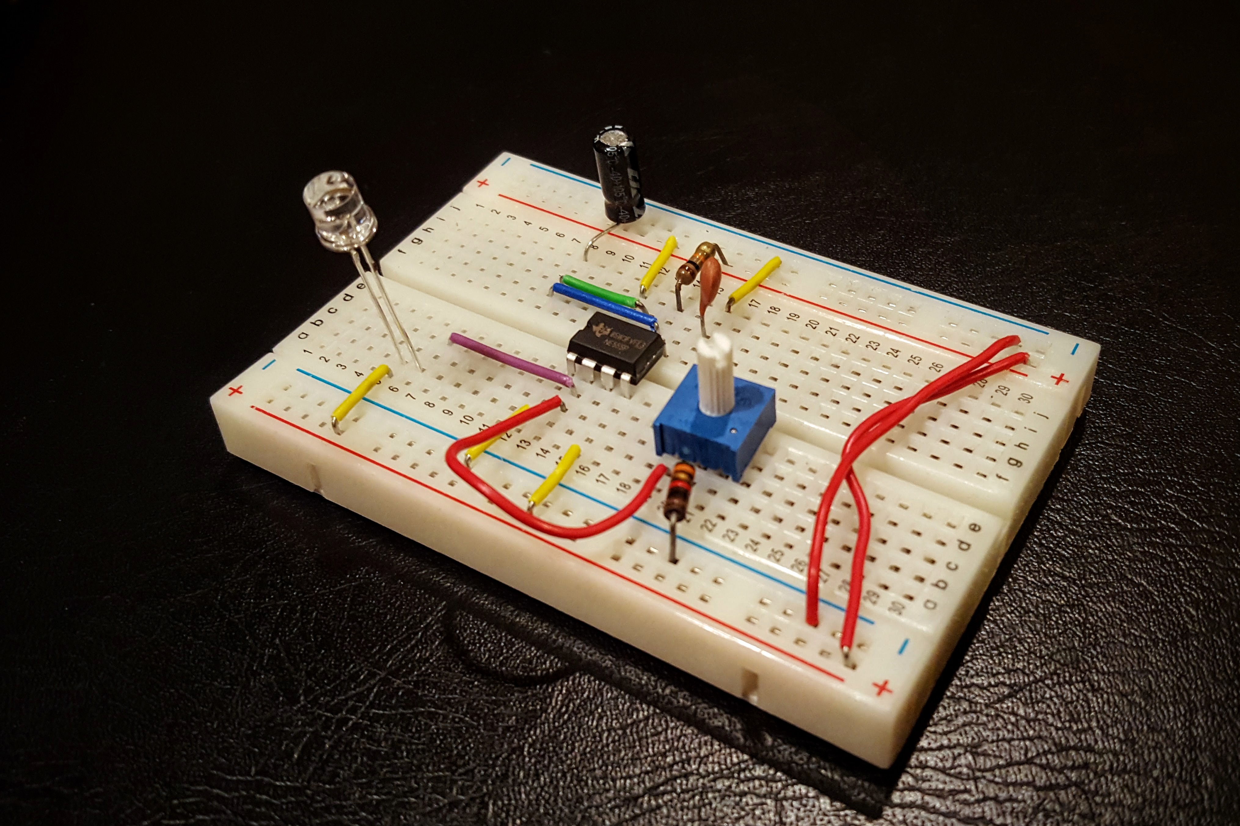
The basic circuit is very simple. I went to TechShop last night and built the breadboard version. TechShop has oscilloscopes so I could debug and look at the timing of the pulse. The potentiometer (R3) was added there to allow me to adjust the sensitivity of the phototransistor based on ambient lighting.
Worked like a charm. The pulse width is about 110 mSec. When I designed the PCBs I thought I’d just be using the phototransistor to generate the pulse so I didn’t design a board for this. I’m going to solder it together on a protoboard and probably won’t bother to do a PCB version.
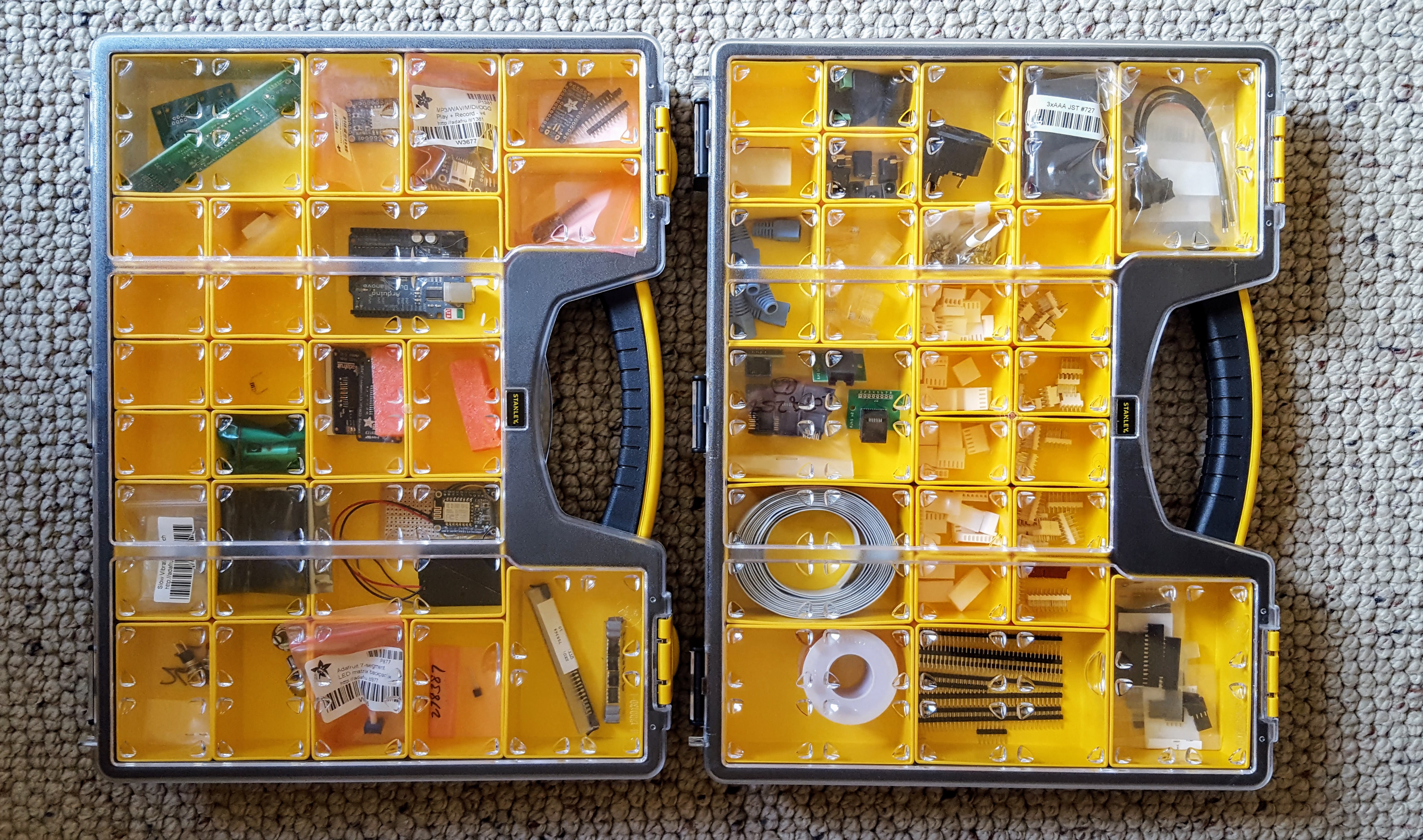
As an aside, I bought a few organizing boxes so I can easily manage all my components. It has the extra benefit of making the whole project extremely portable between my garage, my home office, and TechShop.
* Light ball? I really need a better name than that. It might be a Blaster Beam. I’m open to any suggestions!